|
WA6TJQ ELECTRONIC PROJECTS
PAGE |
![]()
Updated 3-24-2022
|
This page is under development I have been working in the electronics field for over 40 years. I have made or modified most of the radio equipment used on my 220 repeater. I have also designed and built dozens of weather stations, earthquake sensing devices, and many electronic alarm circuits, the first of which was back in the early 1970's. During the 60's 70's and 80's one of the best places to get electronic components and assemblies were military surplus stores. Many were located a few miles from where I grew up in Anaheim California. Back then, you could buy electronic devices previously used by the military for pennies on the dollar. I made my rounds once a week to see what new items had arrived; assemblies with switches and indicator lights were my main interest. I would part-out the units and make windspeed and direction indicators, as well as alarm devices. Windspeed and direction sensors could easily be made using reed switches and coils found in most surplus assemblies. For example, if you placed small magnetic reed switches at 16 points on a circuit board you can make a very accurate wind direction sensor. The 16 reed switches were linked to small DC lamps that correspond to the various compass points for N,S,E,W etc. Light-emmiting diodes (LEDs) were very expensive at that time, selling for around $5.00 each. A variety of DC motors could also be used to indicate indicate windspeed. My first windspeed anemometer was made from ping pong balls cut in half as the wind cups, which were attached to a small DC toy hobby motor using small sections of welding rod. The readout was a DC milliamp meter calibrated for proper windspeed using a simple 1/4 watt 1% resistor. I am sure this is the reason for my interest in Amateur Radio; I built many of my first CW transmitters from used parts purchased from surplus stores across the county. I wound my coils using copper wire that had been discarded and left for the trashman by a neighbor. Vacuum tubes, capacitors, resistors, etc. were tossed out by the local TV repairman and a great source of spare parts...for the right price! In the early 1970's I worked building electronic gas detection equipment for a company called International Sensor Technology. Looking back, I can say this was one of the best companies I have ever worked for. In the early 1980's I worked for Hughes Aircraft and Douglas Aircraft. I learned to wire radar defense systems for the US Government where I built and wired commercial aircraft systems for the DC-9 and DC-10. I also worked on the Air Force version of the DC-10 called the KC-10. Working in the areospace field was a very rewarding experience; wiring jet aircraft was one of the most technical jobs I have ever had, there was always something new to learn! Most of my time was spent wiring the cockpit instrument indicators and metering devices. A few of the commercial aircraft I worked on while at Douglas Aircraft in Long Beach California are shown below. While at Hughes Aircraft Compnay I had the opportunity to work on spacecraft assemblies. Some of the best space satellites were designed and built by Hughes; I haven't come across any photos of the spacecraft but if I find some I will add them to this page. After leaving the areospace industry I worked for a number of telephone and cable TV companies repairing various systems used in the delivery of cable TV and telephone signals. I built and installed some of the first wireless cable systems used to deliver TV programming in the microwave band. Do you remember Z Channel? Yes! I have had experience working with that system- and today you can watch hundreds of satellite channels with just an 18 inch dish! After 6 years I changed careers to the Solid Waste and recycling industries. I've worked for 2 private contractors in San Bernardino County. I now build and sell custom weather station circuits and solar powered controllers. I build small LED lighting displays using vintage electronic parts from my home-based electronics company. I have been an active online Ebay seller since 2000. I offer surplus electronic parts, Ham radio equipment, custom-designed solar controllers, lighting displays using vintage vacuum tubes, and much more! I am in the process of adding a new webpage to this site featuring many of my custom electronics circuits and various items manufactured in my small electronics shop. Thanks and 73'sss Mike WA6TJQ |
| While working for Douglas Aircraft in the early 1980's, I worked on the DC-9 and DC-10 commercial and military jets. My job was wiring the inside cockpit instruments and circuit breaker panels. I also traced hundreds of wires which ran from the nose of the aircraft to the tail section. Thousands of wires, switches, relays, and many other componets working together flawlessly! I have included a few photos below. |
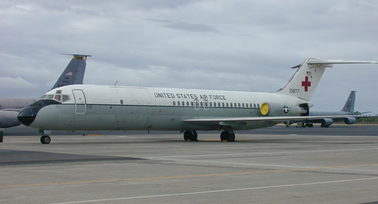
| DC-9 Military Version. This one was used as a Flying Hospital, note the red cross on the tail section, also the addition of large cargo doors used for loading full sized hospital beds and other large equipment. |

| Commercial version of the DC-9. I worked on some of the older DC-9 Models as well as the newer stretched version called the Series 80. I was on hand when the 1000'th DC-9 was produced at the plant in Long Beach, California. (The photo above was not taken in Long Beach) |
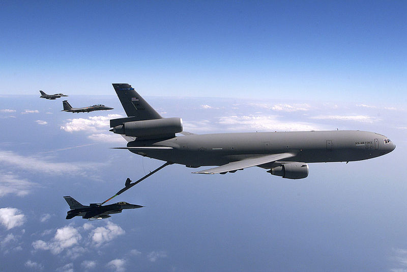
| And here a KC-10
Air refuler, A Military Version of the DC-10 Passenger jet that has been modified
for air refueling. I worked on many sub assemblies and instrument packages for
this aircraft. |

| Commercial passenger version of the DC-10. I was in Long Beach, California the day the first DC-10 took to the sky, what a sight it was as the large jumbo jet lifted off the runway in Long Beach. The jet flew just over Lakewood Blvd, as it gained altitude and turned to the south over the Pacific Ocean. The photo above is not of the first flight of the DC-10 it is just one of many photos of the DC-10 I had avaliable. |
| I have a number of electronic projects on the drawing board I will be adding photos and information as soon as time allows. Below you can see a weather station project that was just completed and is now linked to the repeater. Using touch tones anyone within range of my radio repeater can link to the weather station and receive up to the second weather information taken at the repeaters location. |
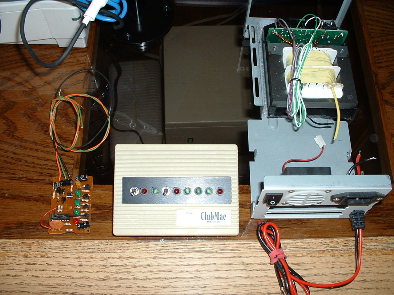
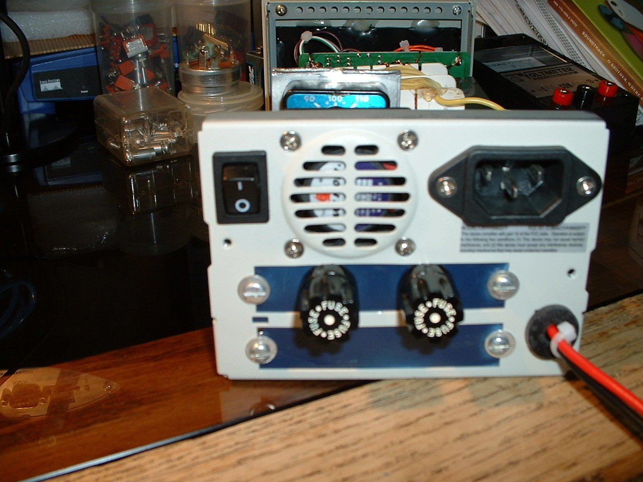
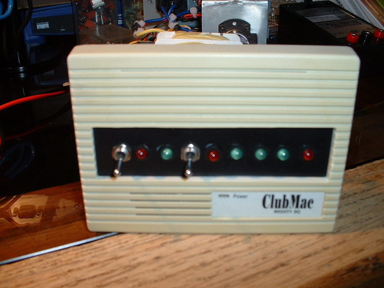
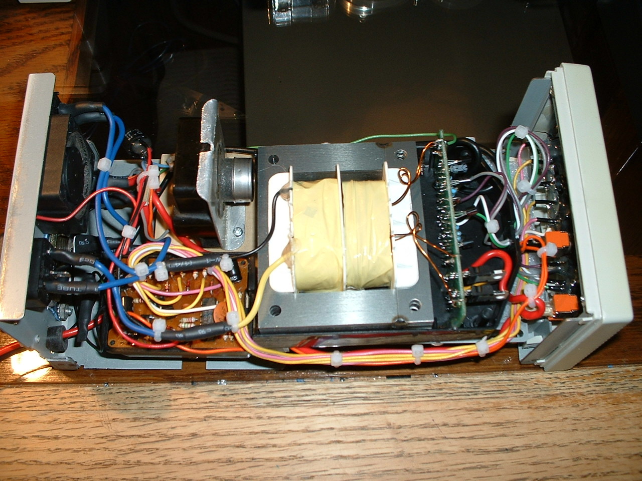
REPEATER WEATHER STATION AUDIO INTERFACE
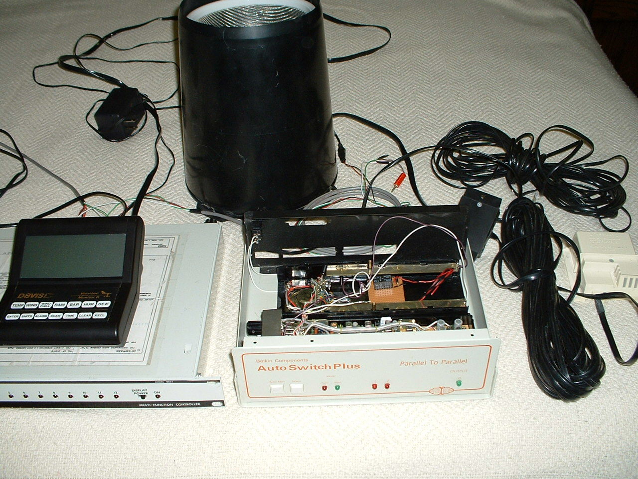
| Here the Davis weather
station as well as the DTMF control box and the 220 transceiver, these have been
modified to work with my 224.560 repeater. When you send the proper dtmf code
to the controller the repeater will send you a full voice based weather report
from the repeater site. |
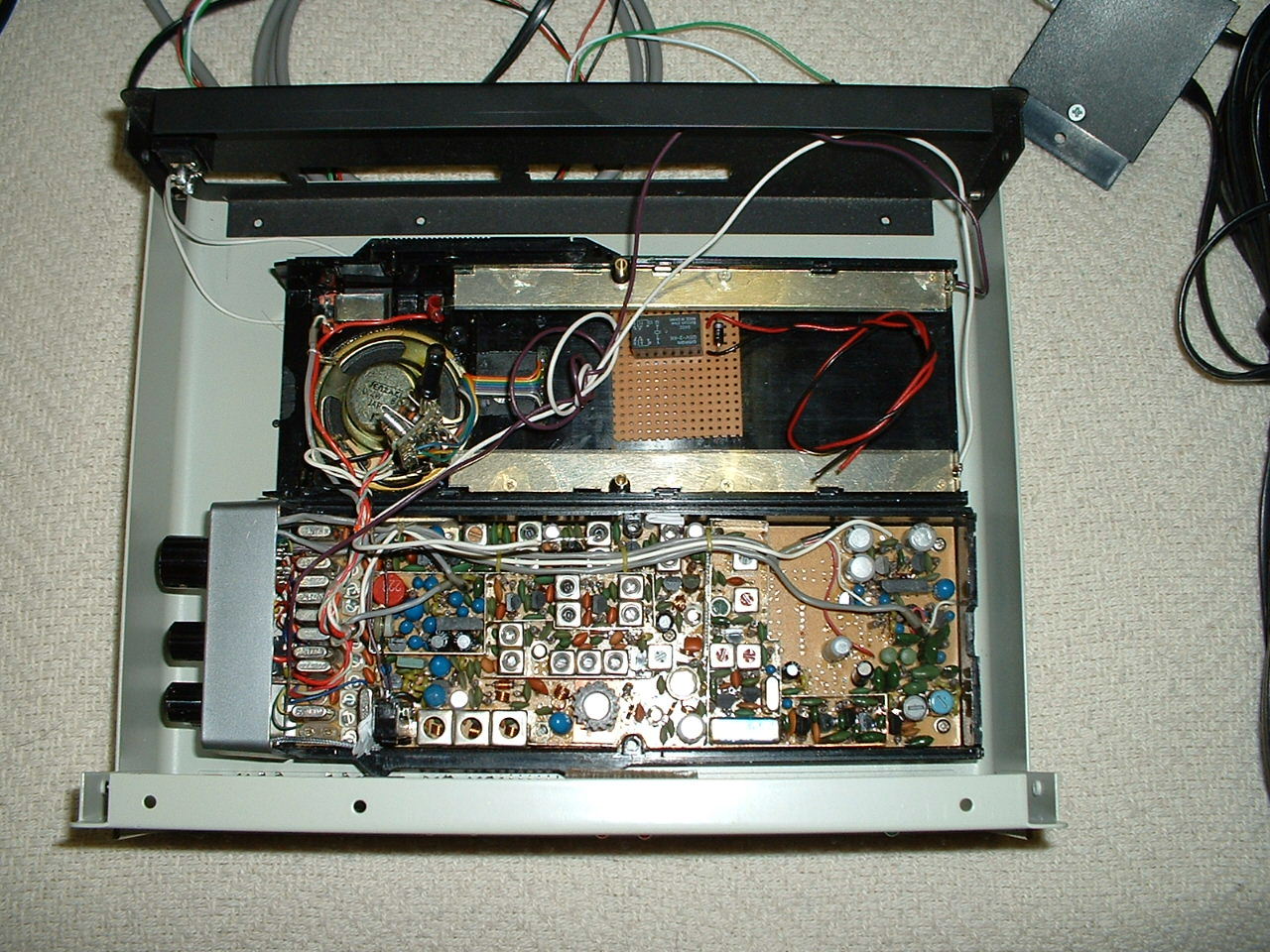
| A look at the old crystal controlled 220 transeiver I modified to work with the repeater. This radio is set up to send audio from the computer that holds the modified audio board, and is linked to the repeaters input frequency. The computer contains a list of voice files that work with the Davis weather station. As the Davis weather station sends updated weather data to the computer, the computer voice files are updated every few seconds and are ready to send a weather report from the repeater site when a user brings up the system. |
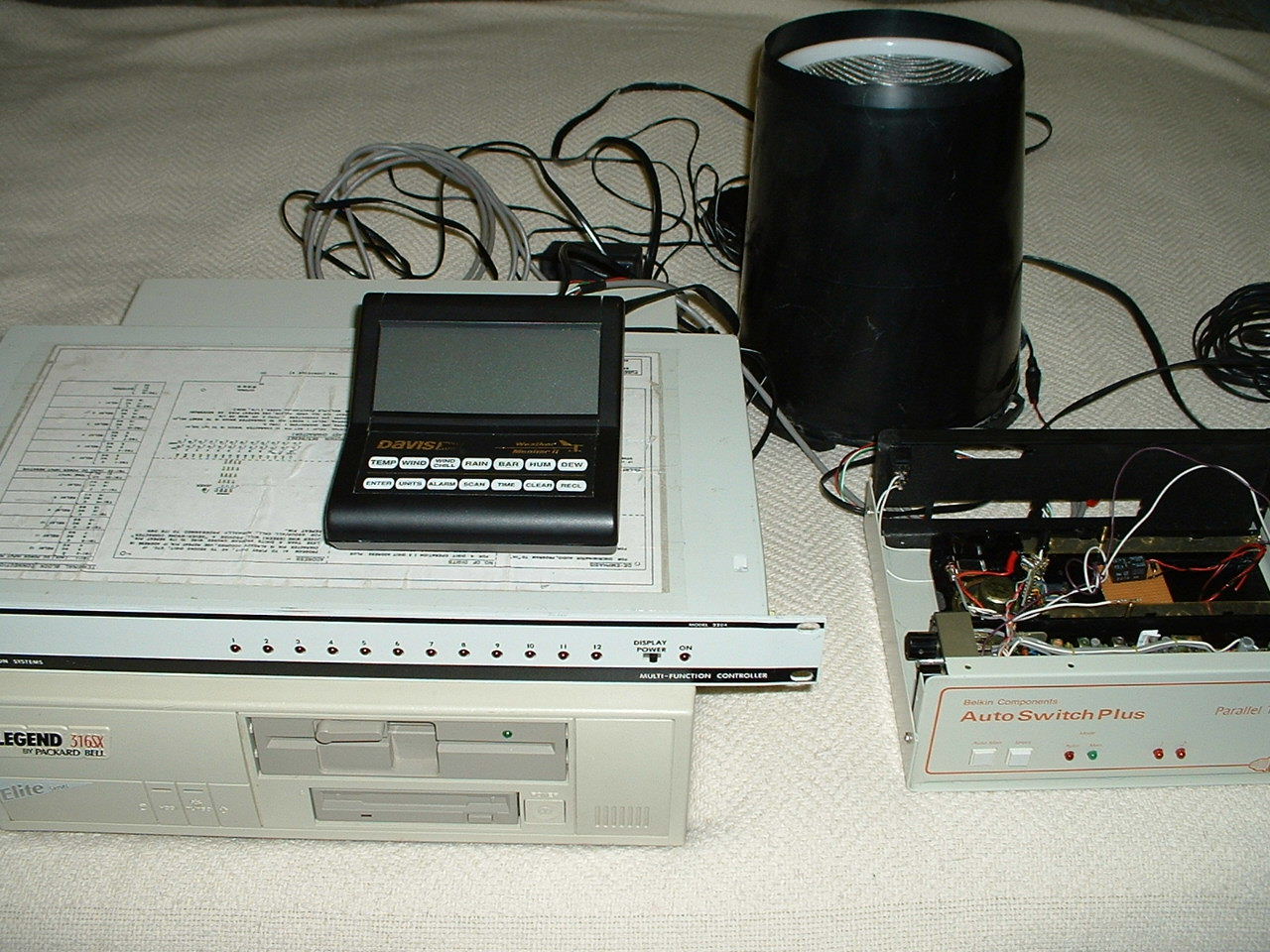
| Older 386 computer with modifications to the parallel port wired to the DTMF box and the weather station and transceiver. The neat thing about this design is that the DTMF controller used for the weather station seen in the photo controls only weather station functions as well as fan cooling on the repeater and a few other functions. It is not the main controller, I have a seperate Scom controller used on the repeater. |
| Modified Davis Weather computer audio card. This card was made by Davis weather company and was sold under the name of (Weather Talker). It was made to interface a Davis weather station to a telephone line, I modified it by tapping off one of the the onboard relays. I added my own 5 volt dc relay that keys the transceiver when the proper DTMF code is received. |
PACKET RADIO WEATHER STATION
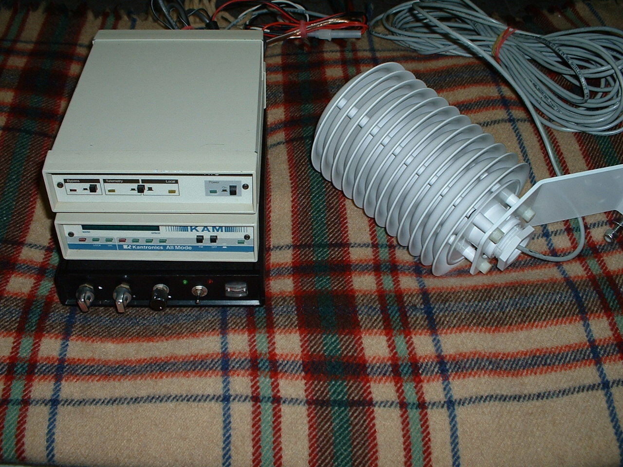
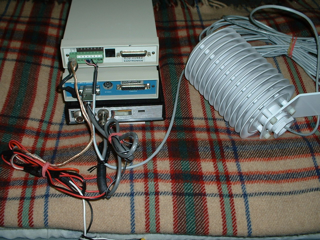
| Here are a few photos of a new radio project I have under way....It is a Packet Radio Vhf Telemetry System. When this project is completed you will be able to receive the Outside Air Temp, Windspeed, Wind Direction, Rainfall, as well as the Temp inside the Telemetry Box via Packet Radio This system is made using a Kantronics Telemetry Unit, with the Wx-Node eprom, a Kantronics Kam Tnc and a Home Brew 2 meter 2 watt low power Vhf transceiver. also in the photo you can see the radiation shield used to protect the outside air temp probe from direct sunlight exposure. The Windspeed and Direction sensor as well as the Rain sensor are not in these photos, but I will add the photos very shortly. |
12 VOLT BATTERY CHARGER PROJECT
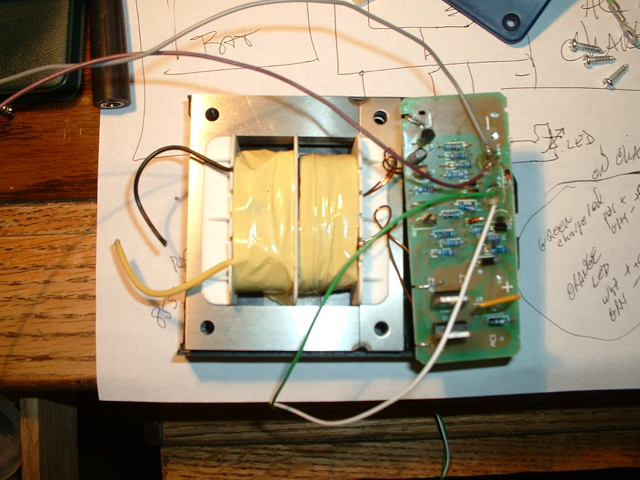
| The charger begins....I bought a $9.99 1.5 amp battery charger from Harbor Freight tool store and just for fun I decided to make the charger far better in design and operation. When I opened it up I found that the AC and DC lines were not saftey protected with fuses...So I wanted to fuse both sides when I re-designed the charger...The (Left) photo shows the charger after I removed it from the box it was in when purchased . The (Right) photo shows the box I found out in my parts shed to install my newly designed charger into ....The box was an old external floppy drive box long since retired, it already had a nice 2 inch 12 volt dc fan inside..and there was a computer AC plug and AC switch already installed on the back. To take advantage of the fan and make the charger even better I installed a thermostat that activates the small cooling fan during the charge cycle if the inside of the charger ever gets above 80 degrees....This keeps the charger cool during charge cycles. You can also see in the (Right) photo a view of the front cover that was on the old floppy drive case, I have added a black plactic cover where the floppy once was installed...On the front of the black plastic I drilled out 9 holes...In these holes I have installed two switches and 7 led's. The purpose of the first switch is to turn on the charge current...Not the charger ac but the chargers DC... I have a seperate switch on the back of the box to turn off the chargers AC...I wanted to have a way to disconnect the DC charge line going to my four 20 amp hour gell cell system...When you switch on the DC charge line the charge circuit senses the battery voltage...When the charger senses a low voltage in the batteries the red led goes off and the charge cycle begins...The green led indicates the charger is operating... The second switch was put in to work my other little gem....The 5 led's to the right of switch number two are made to give you a visual indication of battery voltage. This was done using a little led volt meter I made some years back...The circuit reads the voltage in the batteries and displays this information in the form of colored led's..The first red led indicates a low battery condition..The next three green leds indicate a battery voltage of 12.5 to 14.5 volts...and the last red led indicates a danger level or overcharge condition, if something was to go wrong in the charger circuit...This led volt meter also has a little alarm circuit that sounds if the battery condition gets low or high....
|

| (Left) photo shows the led volt meter circuit ...And the (Right) photo shows the back of the charger...You can see the 2 fuses installed where once there were scsi cable connectors... I took a cover from an old blue plastic electronic box and installed it over the old floppy scsi connector holes...The two fuses are for AC line voltage and for DC charge and battery connection... Also you can see the small vent for the 2 inch cooling fan and the master AC switch to turn off power to the charger...And in the top right of the (Right) photo you can see the ac power connector that was once used for the floppy system...This made for a clean way to get ac power ino the charger... On the bottom right you can see the Red and Black Positive and Negative battery wires ....So the floppy case made a real cool box for this project... |
| The last two photos are
the front panel of the charger seen on (Left) and
the completed charger all ready for the cover to be installed on the
(Right) ...I connected the charger up for testing and it works like a dream...all
automatic and I can watch the front led indicators operating just as they should...This
was a real fun project and it turned a $9.99 Harbor Freight charger into a one
of a kind computer controlled charger complete with auto cooling and led voltage
readout. |
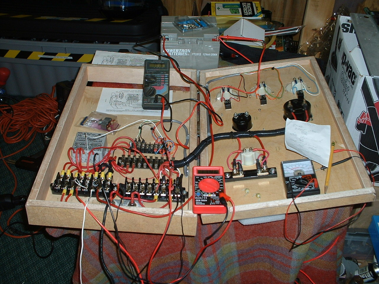
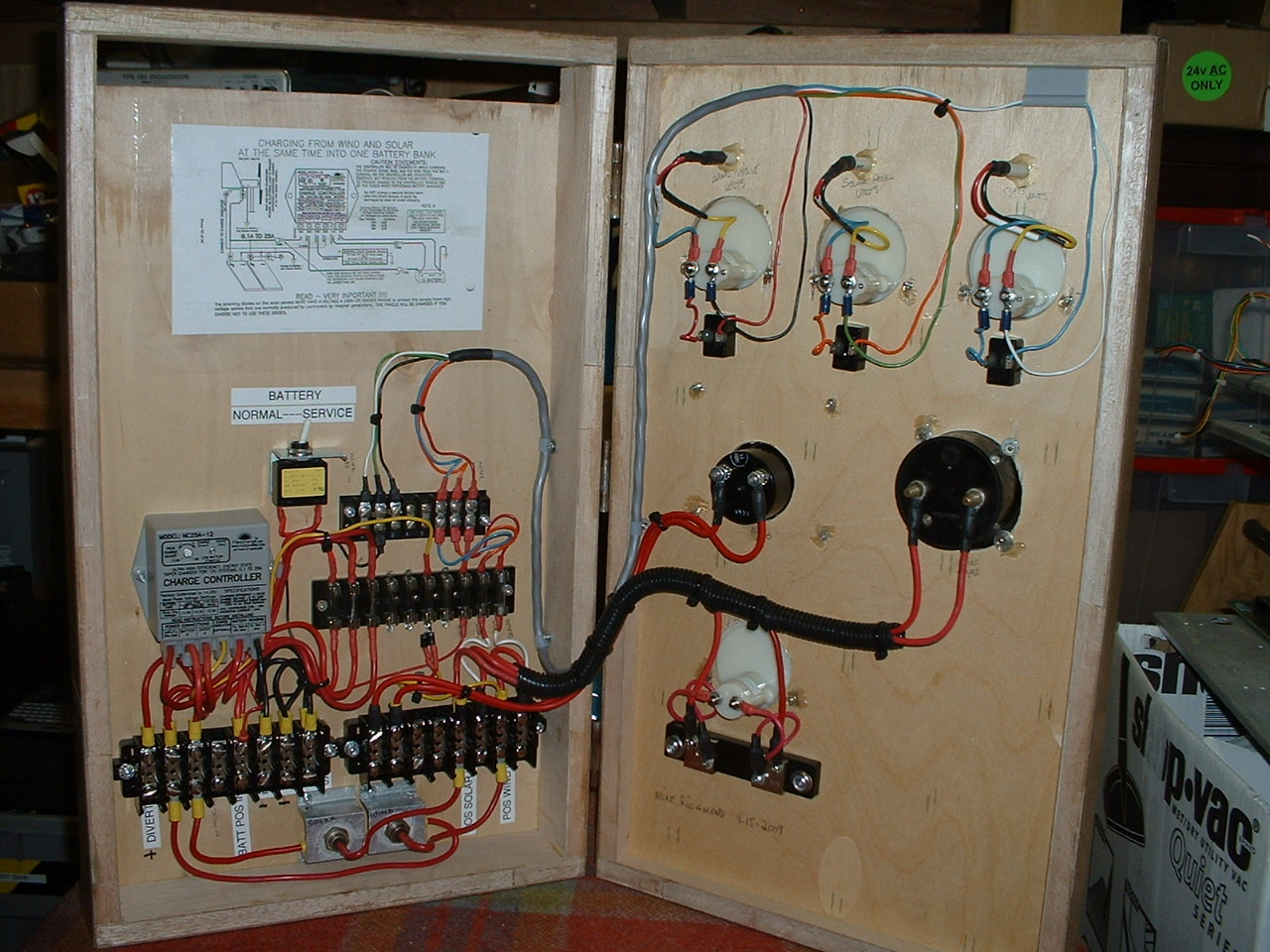
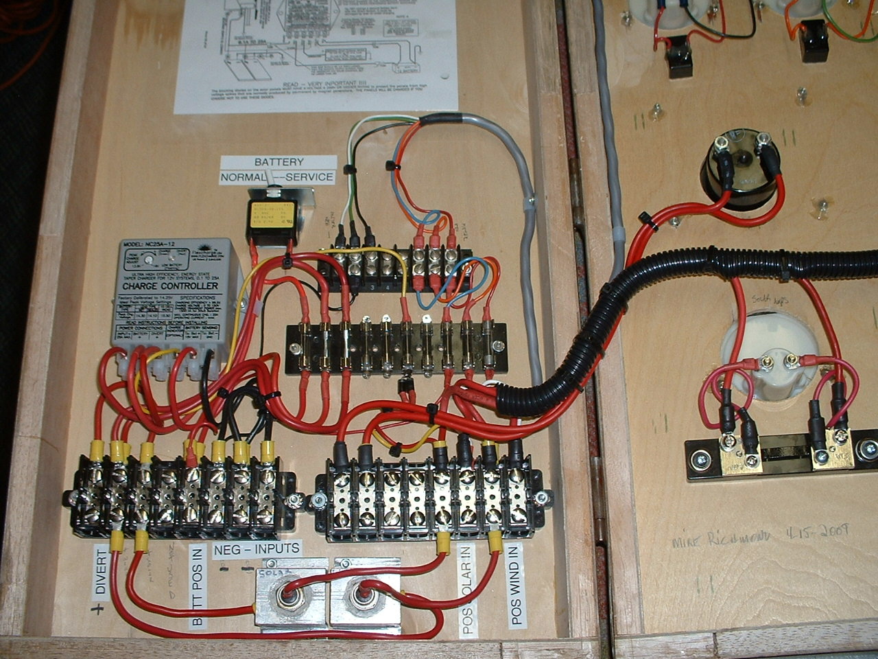
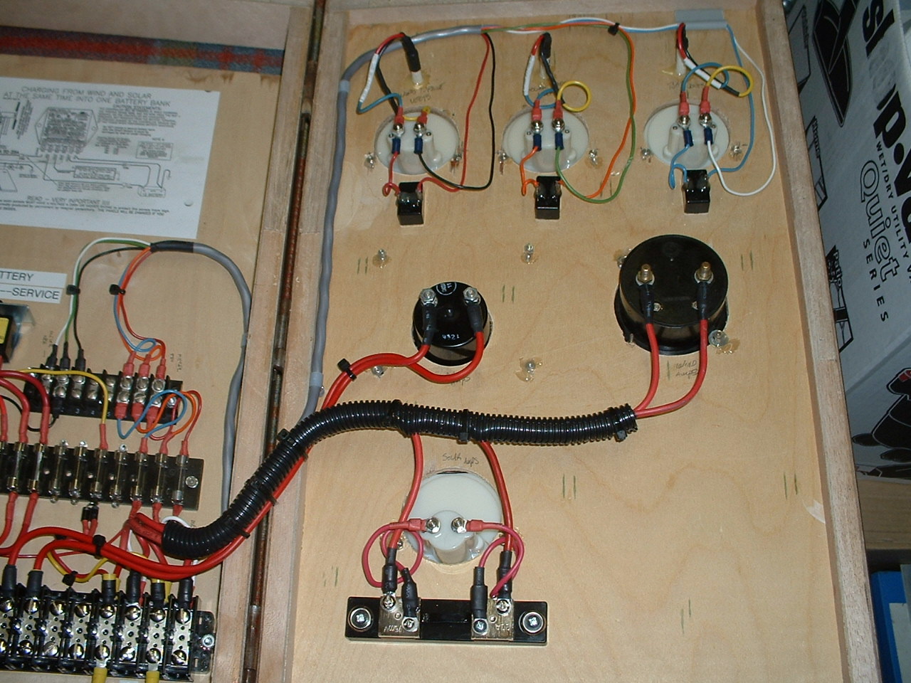
| 12 VOLT
SOLAR / WIND POWER CHARGE CONTROLLER |
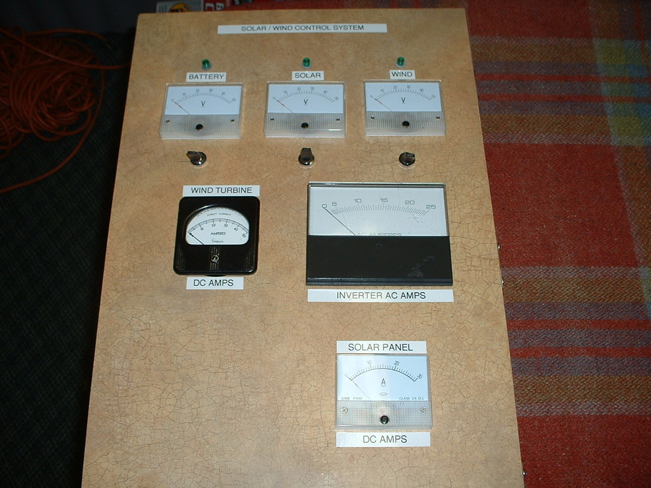
| Here is one of my latest projects...This is a Wind / Solar charge control box I just finished wiring a few days ago. This controller is able to use power generated by both a homebrew 12 volt wind generator, and two solar arrays to charge a small battery bank which in turn powers lights in a friends cabin.... The system was just put online and is working fantastic. The control box was made by my neighbor Carl, He had a custom cabinet shop for years, so he was able to put together a nice enclosure made from plywood. The control box has meters for Wind Generator Volts and Amps as well as Solar Volts and Amps, Battery Volts and AC inverter amps. Everything including the volt meters and led lights are fused. |
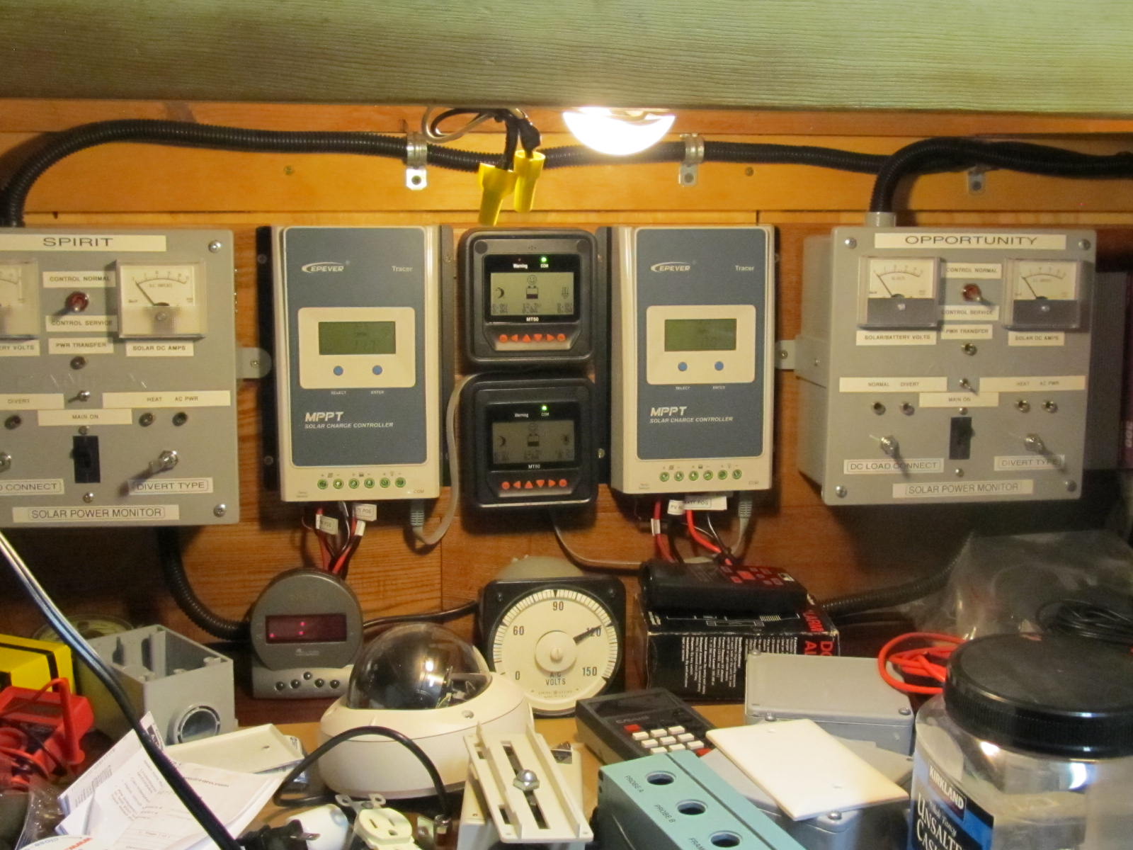
The photo below shows a simple 12 volt solar control system I am building in 2019. It was made using two Tracer MPPT charge controllers, and two custom made meter boxes to measure volts DC and Amps DC and allow me to switch power from charging mode to heating mode. In the heating mode I can heat my small shed workshop with the excess solar power when the battery bank is full. |
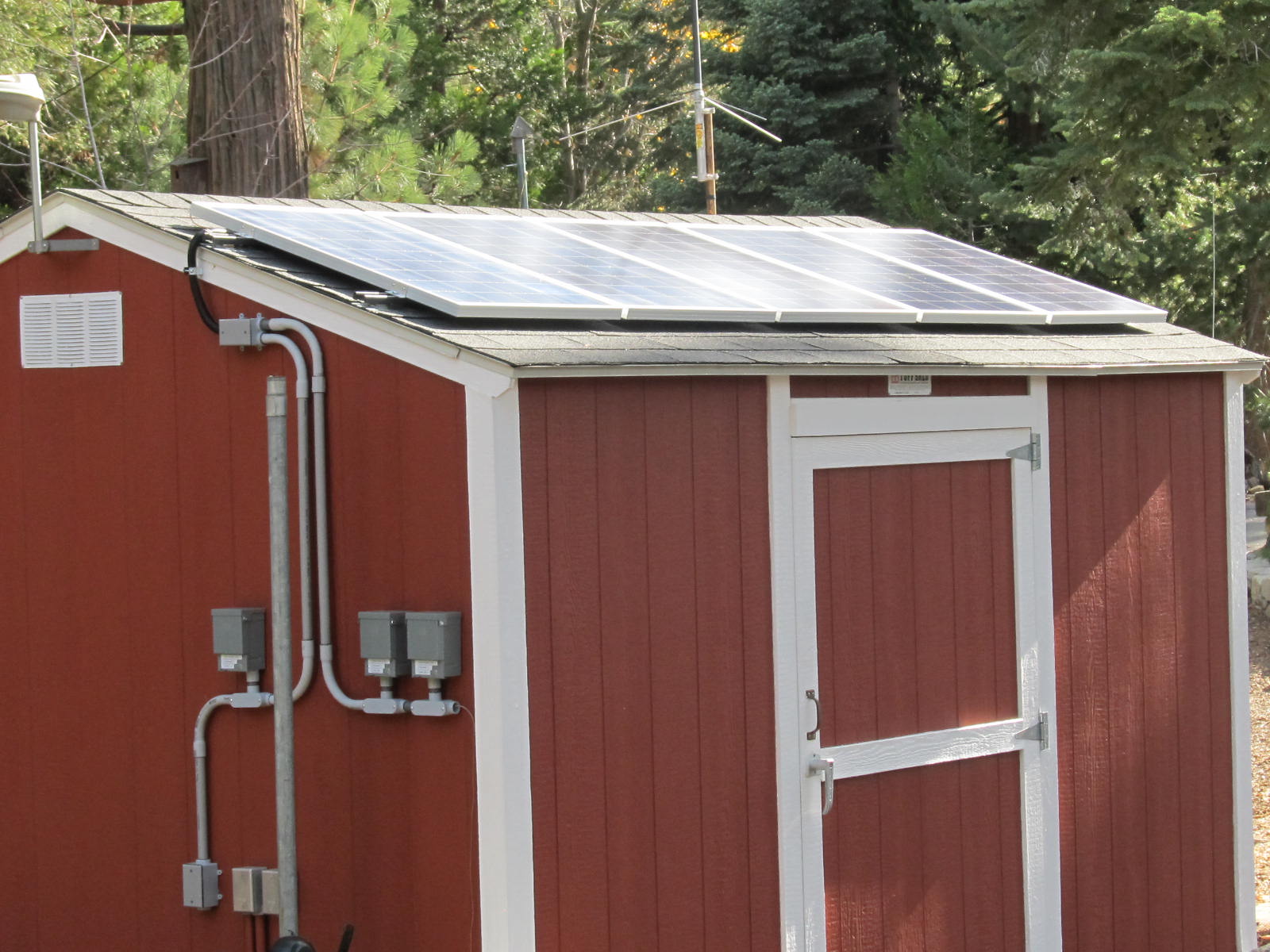
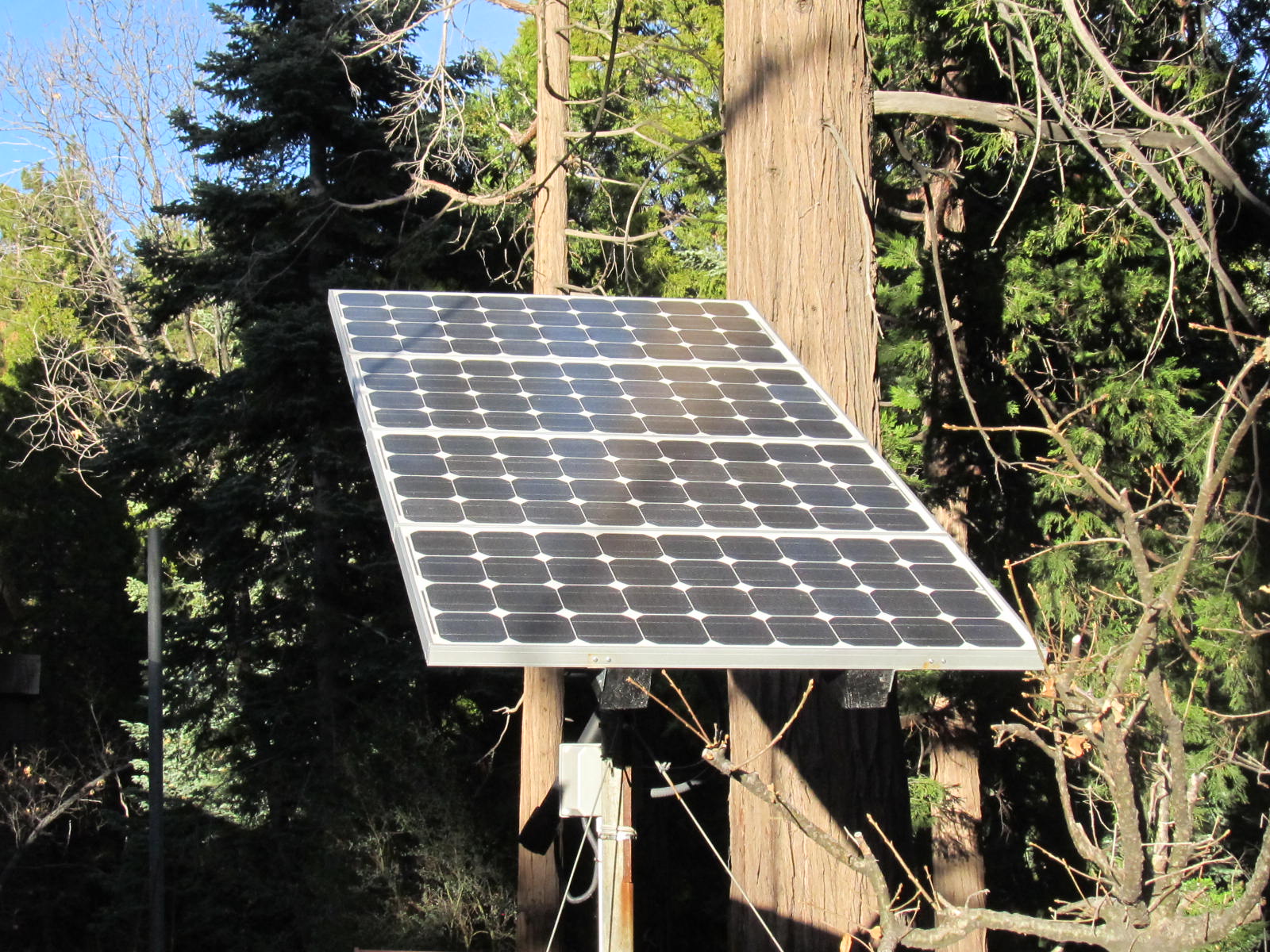
The
two photo's below show a 500 watt and 400 watt
solar arrays, these are connected to the above charge control system and provide
power to run my Ham Radio Packet Network as well as house lignting inside and
out and various other electronics. |

2003-2022 twinpeaksweather.com