| CURRENT
REPEATER SYSTEM |
|
WA6TJQ 220 MHZ REPEATER SYSTEM |
Updated 1-12-2020
| CURRENT
REPEATER SYSTEM |
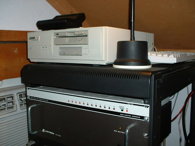
| HERE ARE SOME PHOTOS OF MY CUSTOM BUILT 224.560 REPEATER SYSTEM. The system continues to evolve, equipment installed into the rack can be seen in the photos above The rack holds the main repeater, the backup repeater, as well as the main repeater controller and a second DTMF controller that is used to control extra cooling fans, amplifier, as well as the repeaters on site weather station. Also installed in the rack is the Astron 35 amp power supply used to power the amplifier, The repeater itself is powered by solar and wind energy. |
|
REPEATER SYSTEM DURING CONSTRUCTION PHASE. |
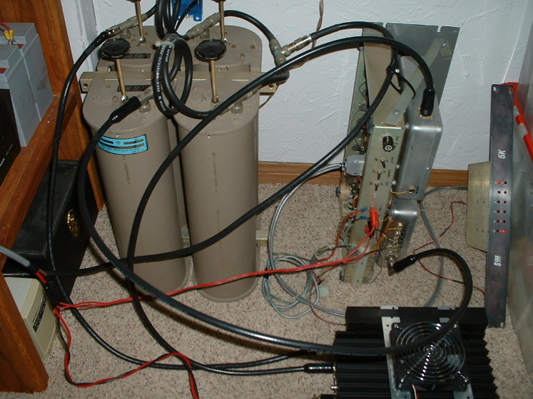
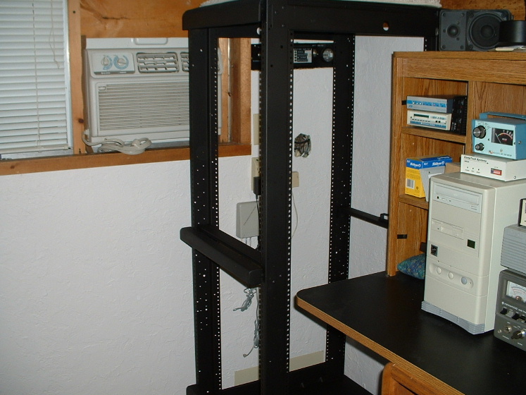
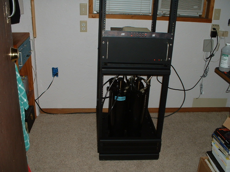
| (Left Photo) Repeater and equipment set up on the floor during testing. The system will be inserted into the radio rack you see in the photo to the right, as soon as I have run all testing to make sure the settings are just right, and to enable me to remove any bugs that might be ready to cause problems in the future. (Right Photo) Here you see the repeaters equipment rack that is awaiting the repeater and equipment. I had this rack sitting outside for 7 years before I had a use for it. With a sanding and a fresh coat of paint, it is good as new. |
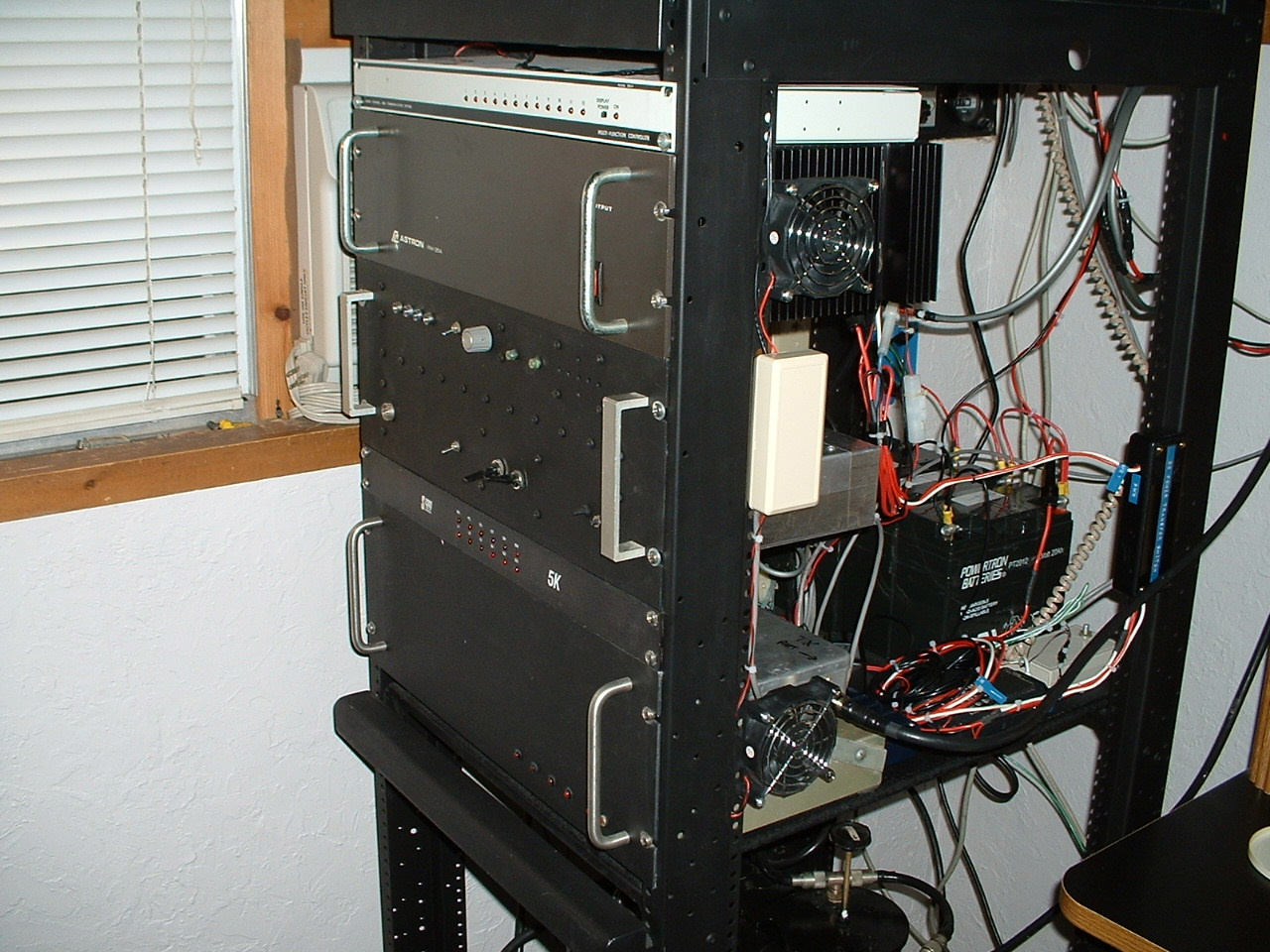
| Ok here is a few photos of the main repeater, The (Left Photo) is going to be used as the new case for my second DTMF controller that will be used to activate fans, weather station audio and other functions. I need to add a few heavy duty 30 amp relays to switch the amplifier on and off and the current DTMF case will not be big enough. The (Right Photo) is of the repeater after the repeater and duplexer were painted and then installed into the rack. Right above the repeater is the scom 5k controller. The repeater is nothing fancy, but it does work fairly well if you take into account the current location of the system. In the future I hope to switch to converted GE Master II radios for both the main and backup repeaters. But you have to start somewhere and for now this is the repeaters current configuration. |
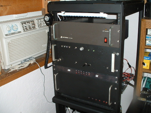
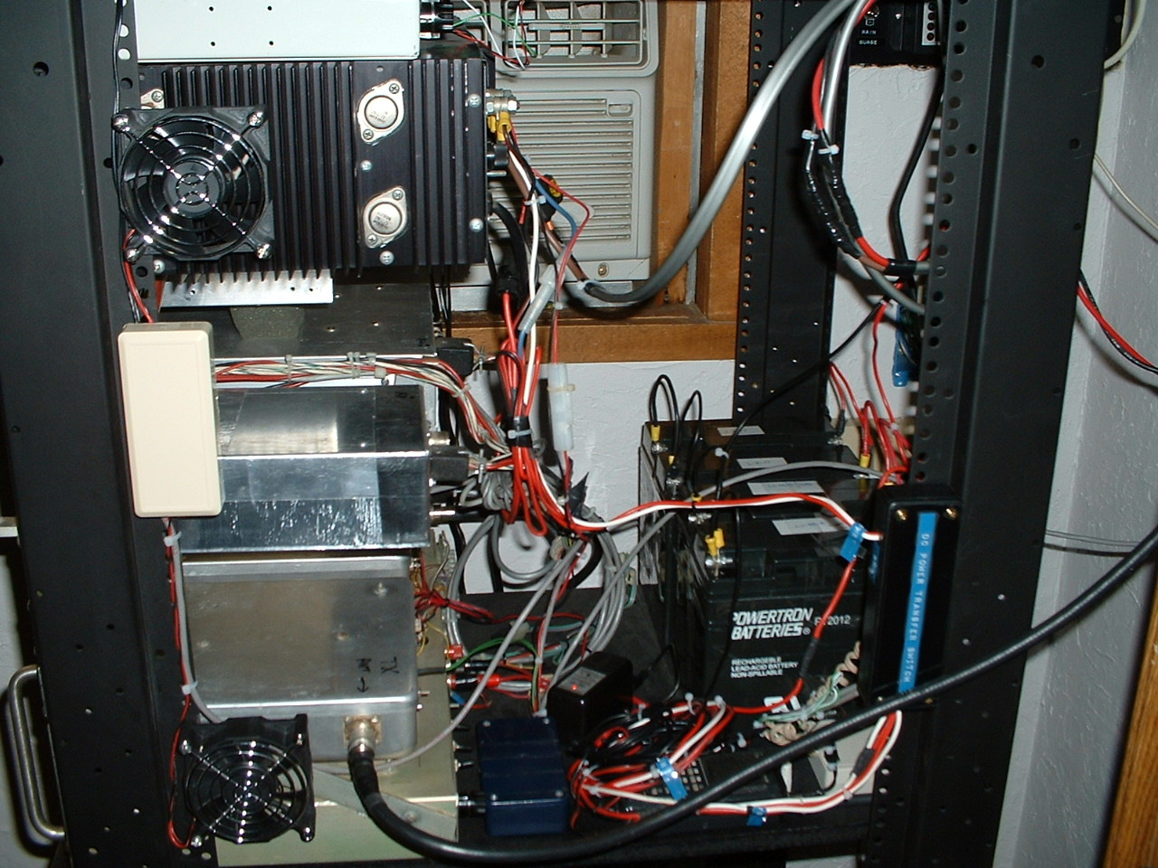
| Photo
on the left shows the Backup repeater installed at the top. The Right photo shows
the new Astron 35 amp power supply which was just added to the system to power
a 120 watt amplifier, Currently the amplifier is set to output 50 watts. I like
the idea having the system running entirely on wind and solar energy. But the
amplfier and power supply must use ac power to operate due to their heavy current
drain, so if grid power fails the amp and the astron power supply will not be
operating and the repeater will remain on as it uses solar and wind power, the
repeaters output on solar and wind power is 15 watts. |
| WA6TJQ
224.560 MAIN REPEATER SYSTEM |
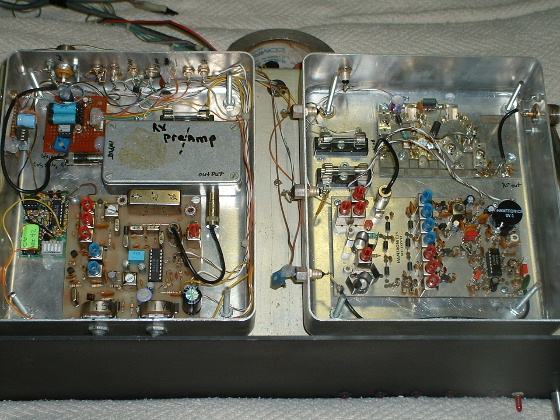
| This is the (Main Repeater), made up of homebuilt Hamtronics 220mhz transmitter, receiver, as well as a homebuilt Hamtronics 220 mhz preamplifier and 15 watt Rf Power amplifier. The first box in the (Left) photo shows the Hamtronics receiver and 220 mhz preamp, also inside this box is a Com Spec TS32 pl board and a few homebrew voltage regulator boards and switching circuits. Also seen in the (Left) photo is the Hamtronics 220 mhz transmitter board, and Hamtronics 15 watt Rf power amplifier. The optional crystal oven was also added to the transmit crystal for frequency stability. In the (Right) photo you can see the underside of the main repeater, This is where the Spec Com phone patch is located, this phone patch will soon be used to interface a talking weather station, and controller so users can bring up weather data at the repeater site. Also in the photo you can see the hookup for the S-Com controller as well as a few more voltage regulator, and switching circuits. |
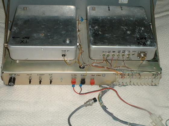
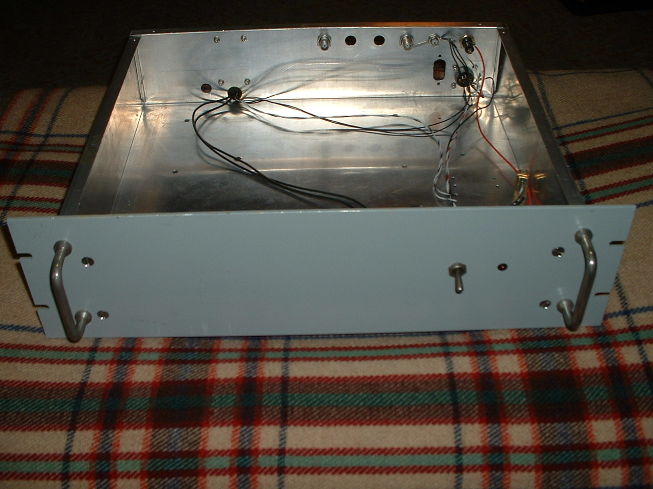
| (Left)
photo shows the back hookups and control switches for the main repeater. In the
(Right) photo you can see the 440mhz control receiver, This is made up of a homebuilt
Hamtronics 440 receiver and a Com Spec TS-32 pl board. The repeaters controller
can be controlled on 440mhz, without going through the repeater 220mhz input. |
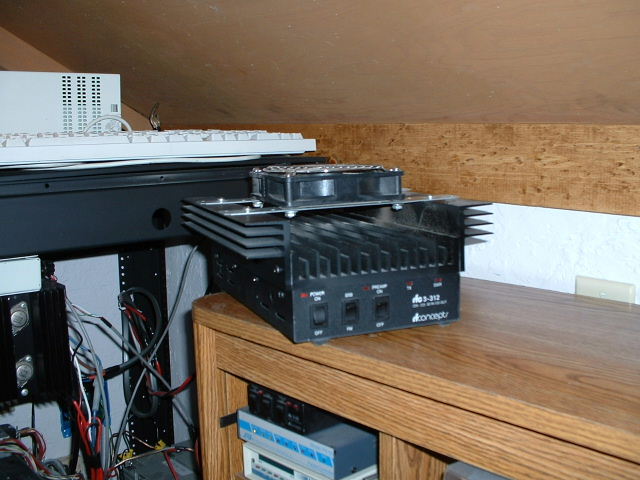
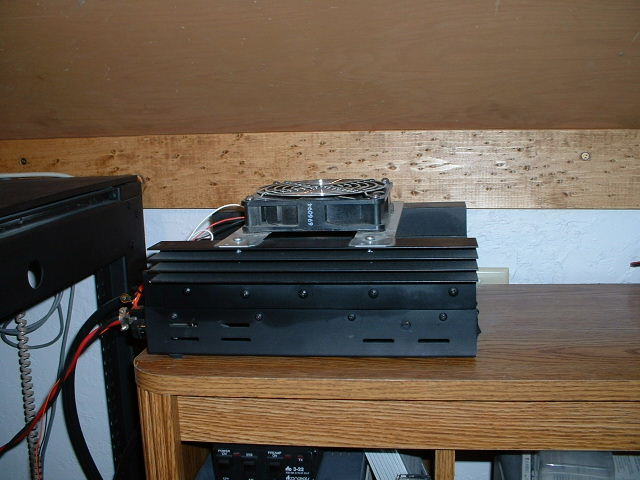
| (Left photo) Front of RF Concepts 3-312 amplifier showing the added heatsinks and fan. (Right photo) Side view of amplifier. I added 2 extra large heat sinks, and a temp controlled cooling fan to the amp. The repeater remains solar and wind powered, but the amp relies on a 35 amp a rack mount Astron power supply. The amplifier is being driven at 1/2 its rated input and has an output of 60 watts...a little over 50 after leaving the duplexer. Later this year the amplifier will be linked to the new DTMF decoder and users will be able to turn the amp on and off via touch tones. |
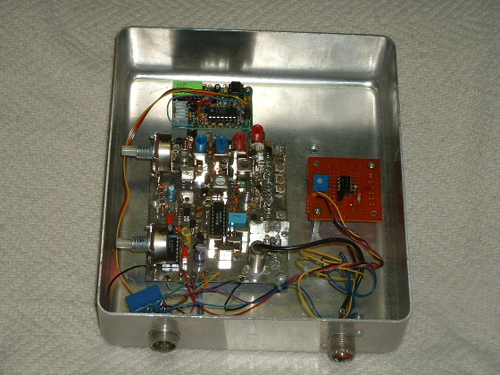
| (Left
photo) Shows main repeater just before it was installed into the rack,
The (Right photo) shows the added 2nd DTMF controller and the computer linked
to the repeaters New Davis Weather Monitor II weather station. The DMTF controller
is able to control 12 seperate functions and is currently set to activate the
repeaters weather station when a user inputs the correct DTMF tone. Also
extra cooling fans as well as the amplifier are being wired to this DTMF controller
so they can be switched on and off. |
| WA6TJQ
224.560 BACK UP REPEATER SYSTEM |
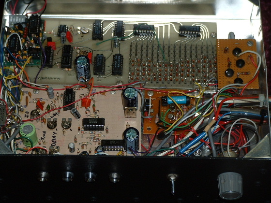
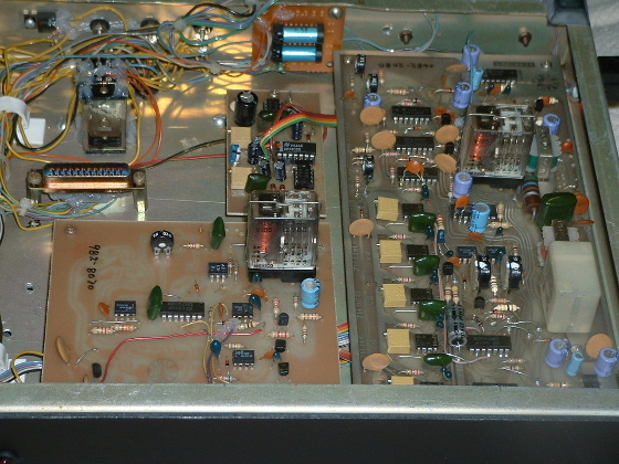
| The two photos above show
the inside of the (Backup Repeaters) controller, made up of Hamtronics and various
homebrew boards. The CWID board made by Hamtronics is an older diode matrix programmable
board, this is the board seen in the back of the controllers box. To the left
of the CWID board there is a Com Spec TS32 pl board, and up front is the Hamtronics
COR-3 repeater controller. On the right you can see a few home brew voltage regulator
boards, and switching circuits. |
|
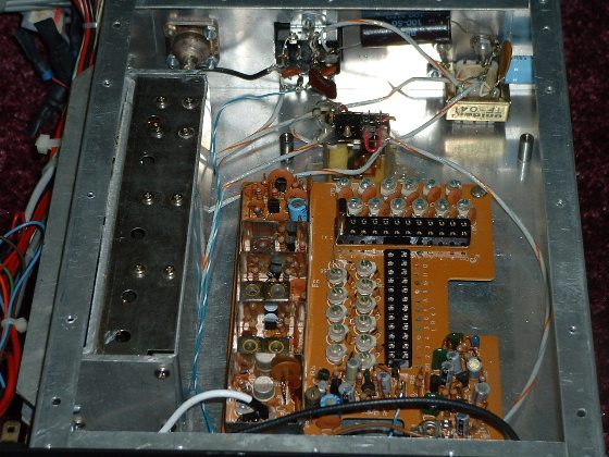
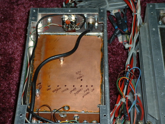
The backup repeater is made from a ( Midland 13-509) crystal controlled 220
mhz radio. In the (Left) photo you see the repeaters (Transmit Board), and (RF
Power Amplifier). The repeater puts out 10 watts and I have added a few extra
heatsinks to the side of the metal box which are connected to the original heatsinks
on the amplifier. The (Right) photo shows the receiver section of the repeater,
the receiver is installed inside a homebrew copper box which makes a nice shielded
install between the transmitter and receiver. |
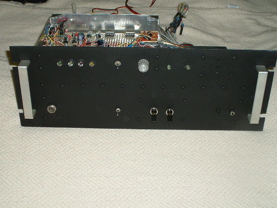
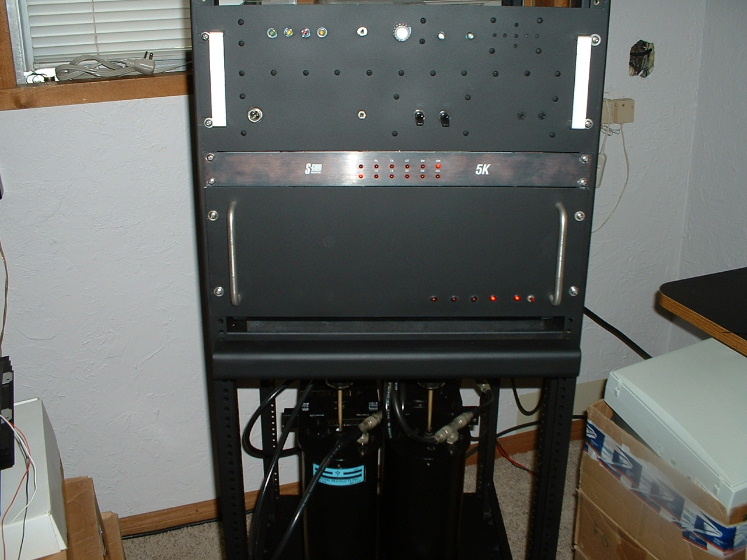
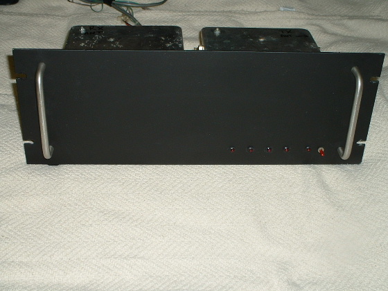
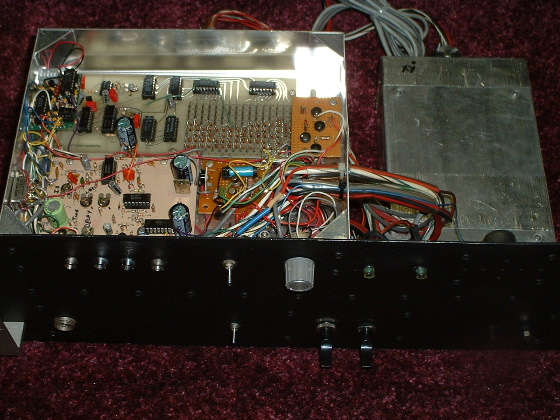
| The
front of the (Backup Repeater), just before it was installed into the repeater
rack along with the main repeater system. The leds on the top left indicate the
repeater controller status. other various switches and controls for the local
and repeat functions, as well as controls for the volume and pl circuits can be
seen. |
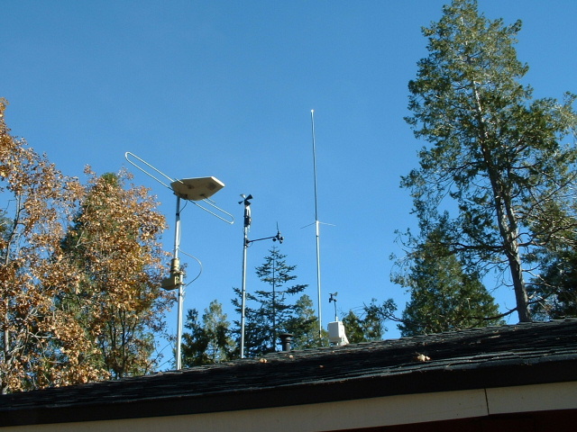
| North side of the house, the old 220 antenna can be seen at the last pole on the right, the antenna height is up 45 feet. |
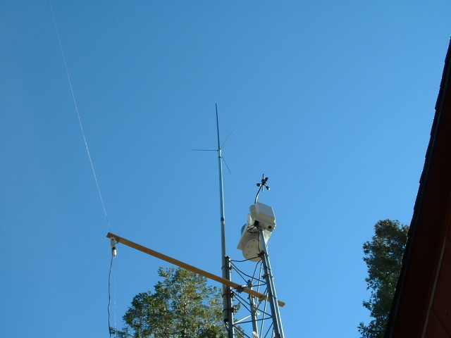
| Here
is a photo of the 220 Comet Supper 22 antenna I have been using on the repeater
for the last 2 years it has 6.6db gain. |
Link To My
Weather Station Website ![]()
2003-2020 twinpeaksweather.com